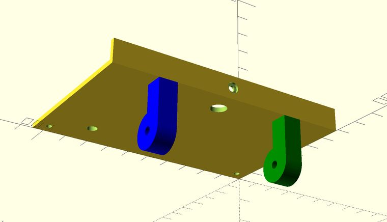
I just re-discovered OpenSCAD. I say 'rediscovered' because I knew it existed, I just didn't know I liked it so much. It took finding a book called "Mastering OpenSCAD" by Jochen Kerdels to get me over the hump. The text of the book is available online as well. I bought the paper copy as a way of thanking the author for helping me jump the learning curve.

I made this back cover for a 20x4 LCD housing I created in Sketchup.
I know in a previous post I promoted the benefits of Sketchup as a modeler for 3D printing, and I don't back down from that position, but I must say I'm really growing fond of OpenSCAD now that I'm getting more familiar with it.
There's one thing I can do with OpenSCAD that we will never be able to do with a Sketchup model. It's sharing like this:
// Dr.Gerg's Pi LCD Mount
// 24x4 LCD Display Box Back Panel
// OpenSCAD definition file
// https://www.drgerg.com
// PARAMETER DEFINITIONS
flat = [104.65,68.75,2];           // LARGER PORTION
up = [104.65,2,10];                // SMALLER RIGHT ANGLE PORTION
leg = [18.886,8,8];                // SQUARE LEG EXTENSION
hinge = 14.5148;                   // ROUND LEG END
hDia = 2.6;                        // SMALL HOLES DIAMETER
hMargin = 3.7 + hDia/2;            // SMALL HOLES MARGIN
h_offset = leg.y - (hinge / 2);    // HINGE PIVOT HOLE OFFSET
//
// LEG MODULE DEFINITION
//
module Leg(){                   // LEG DEFINITION
    difference(){
        union(){
            $fn = 48;              // LEG EXTENSION
            translate([0,0,0])     //($fn increases the number of faces)
            rotate([0,90,0])
            cube(leg);

            translate([0,h_offset,-leg.x])  // PIVOT OR HINGE BODY
            rotate([90,0,90])
            cylinder(8,d=hinge,true);
        }
            $fn = 48;                      // PIVOT HOLE
            translate([-2,h_offset,-leg.x])
            rotate([90,0,90])
            cylinder(12,d=3.3,true);
    }
}
// MAIN BODY OF BUILD
// COMPONENT BODY DEFINITION
//
union(){                                    // MAKE EVERYTHING A UNIT (MANIFOLD)
difference(){                               // TO CUT OUT THE HOLES
        union(){                            // MAKE THE TWO FLAT SECTIONS A UNIT
        cube(flat);                         // START WITH BIG FLAT PIECE
        translate([0,66.75,0])
        cube(up);                           // ADD SMALLER RIGHT ANGLE PIECE
        }                                   // NOW 'DIFFERENCE' THE HOLES
        translate([hMargin,hMargin,-1])     // BACK TOP LEFT SCREW HOLE
        cylinder(flat.z+4, d=hDia,true);

        translate([flat.x-hMargin,hMargin,-1])          // BACK TOP RIGHT SCREW HOLE
        cylinder(flat.z+4, d=hDia,true);

            translate([flat.x/2,flat.y+2.5,up.z/2])     // BOTTOM SCREW HOLE SHANK
            rotate([90,0,0])
            cylinder(5,d=hDia,true);

            translate([flat.x/2,flat.y+4,up.z/2])       // BOTTOM HOLE COUNTERSINK
            rotate([90,0,0])
            cylinder(5,d=4.6,true);

            $fn = 48;
            translate([flat.x / 2,flat.y -10,-6])       // WIRE HOLE DEFINITION
            rotate([0,0,0])
            cylinder(12,d=7,true);

            translate([flat.x - 20.5,13,-6])            // SCREWDRIVER HOLE DEFINITION
            rotate([0,0,0])
            cylinder(12,d=4.54,true);
}
// UNCOMMENT FOR LEGS PARALLEL TO BACK
//
// translate([flat.x - 19.3,flat.y,leg.y])
// rotate([90,180,0])
// color("violet")
// Leg();

// translate([leg.y + 19.3,flat.y,leg.y])
// rotate([90,180,0])
// color("red")
// Leg();

// UNCOMMENT FOR LEGS PERPENDICULAR TO BACK
//
translate([flat.x - leg.y - 19.3,flat.y - leg.y,0])
color("blue")
Leg();

translate([19.3,flat.y - leg.y,0])
color("green")
Leg();

// LEAVE FOLLOWING CURLY BRACKET UNCOMMENTED
}
That is the entire file that creates the 3D object in the screenshot above. I think that's pretty awesome.
Another aspect of using OpenSCAD for building things like this is that I can edit the code in Visual Studio Code, and set the OpenSCAD app to automatically refresh when the code file is saved. So, VSCode in one window and the 3D visualization of the object in another. It's the best of both worlds.
All in all, I'd say with no hesitation that OpenSCAD and Prusa is another Thing That Works.
