This post is a listing of the OpenSCAD code for the 3D printed parts of the LCDPi. Slideshow at the bottom.
This is PiddlePi, one of the P*Pi's. 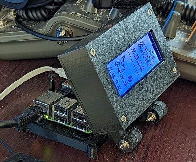
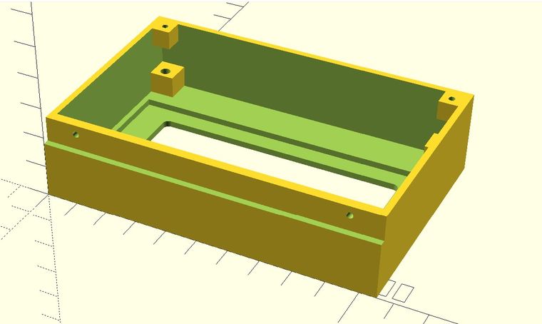
Here is the main body file. I have it saved as "2004 LCD case.scad".
// Dr.Gerg's Pi LCD Mount
// 24x4 LCD Display Box
// OpenSCAD definition file
// https://www.drgerg.com
// OpenSCAD Cheatsheet http://www.openscad.org/cheatsheet/index.html
use <2004 LCD Back v5.scad>;
use <3mmSocketHeadHole.scad>;
// PARAMETER DEFINITIONS
body = [105,69,26]; // Main exterior shell.
hollow = [101,64,28]; // Cutter to hollow the box.
zwall = [107,4,12]; // Cutter for exterior indention on bottom edge.
zwall2 = [105,3,11]; // Defines final indented wall on bottom edge.
lcdbody = [97.5,40,6]; // Indention for the body of the LCD.
lcdface = [75,25,10]; // Opening for the face of the unit.
standOff = [9,9,9]; // Four corner standoffs.
lcdMntSpacingH = 93.2; // Horizontal (X) distance between mount hole centers on LCD.
lcdMntSpacingV = 54.8; // Vertical (Y) distance between mount holes.
L_bottomSH = 10; // Horizontal (X) spacing for bottom screw holes
R_bottomSH = 10; // Horizontal (X) spacing for bottom screw holes
//
//
//// FRONT LCD OPENING MODULE DEFINITION
//
module frontOpening(){
minkowski(){
$fn=48;
cube(lcdface);
cylinder(d=4,h=10);
}
}
module mountHole(){
difference(){
cube([6,6,6],true);
$fn=48;
translate([0,0,-12])
cylinder(28,d=2,false);
}
}
// OPTIONAL BACK. Position the back on the case.
//
module back(){
rotate([180,0,0])
translate([0,-body.y,-body.z-2])
LCDBack();
}
//#back(); // Uncomment to see the back applied to the model.
//
//// MAIN BODY OF BUILD
// COMPONENT BODY DEFINITION
//
module main(){
union(){ // MAKE EVERYTHING A UNIT (MANIFOLD)
difference(){
cube(body); // Main Shell.
translate([2,3,4])
cube(hollow); // Hollow.
translate([-1,-2,18])
cube(zwall); // Upper front wall cutter.
translate([body.x/2 - lcdbody.x/2,body.y/2 - lcdbody.y/2,2])
cube(lcdbody); // Depression cutter for LCD body.
translate([body.x/2 - lcdface.x/2,body.y/2 - lcdface.y/2,-2])
frontOpening(); // Opening cutter for LCD screen.
}
translate([0,2,15])
cube(zwall2); // Upper front wall interior extension.
translate([5,body.y-5,body.z-3])
mountHole(); // Left top mount screw hole.
translate([body.x-5,body.y-5,body.z-3])
mountHole(); // Right top mount screw hole.
}
}
difference(){
union(){
main();
translate([1,1,2])
cube(standOff,false);
translate([body.x - standOff.x -1,body.y - standOff.y - 1,2])
cube(standOff,false);
translate([body.x - standOff.x - 1,1,2])
cube(standOff,false);
translate([1,body.y - standOff.y - 1,2])
cube(standOff,false);
}
$fn=48; // Give me more sides!!
translate([body.x-L_bottomSH,12,body.z-3])
rotate([90,0,0])
cylinder(20,d=2,true); // Left front screw hole.
translate([R_bottomSH,12,body.z-3]) // (In use this is really the bottom.)
rotate([90,0,0])
cylinder(20,d=2,true); // Right front screw hole.
translate([body.x/2 - lcdMntSpacingH/2,body.y/2 - lcdMntSpacingV/2,-1])
SocHdHole();
translate([body.x/2 - lcdMntSpacingH/2,body.y/2 + lcdMntSpacingV/2,-1])
SocHdHole();
translate([body.x/2 + lcdMntSpacingH/2,body.y/2 - lcdMntSpacingV/2,-1])
SocHdHole();
translate([body.x/2 + lcdMntSpacingH/2,body.y/2 + lcdMntSpacingV/2,-1])
SocHdHole();
}
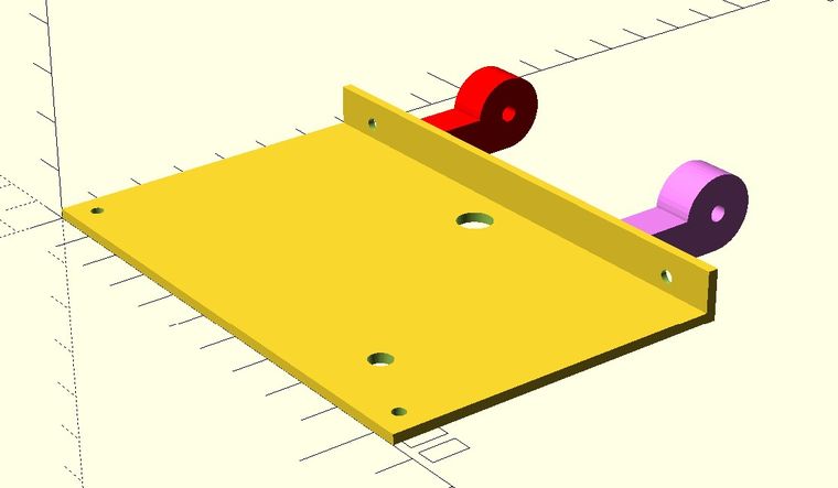
Here is a listing for the back module. Save it as "2004 LCD Back v5.scad". The case file depends on this file being named exactly that way.
// Dr.Gerg's Pi LCD Mount
// 24x4 LCD Display Box Back Panel
// OpenSCAD definition file
// https://www.drgerg.com
// OpenSCAD Cheatsheet http://www.openscad.org/cheatsheet/index.html
//
// PARAMETER DEFINITIONS

flat = [105,69,2];                  // LARGER PORTION
up = [105,2,10];                    // SMALLER RIGHT ANGLE PORTION
leg = [19,8,8];                     // SQUARE LEG EXTENSION
hinge = 15;                         // ROUND LEG END
hDia = 2.6;                         // SMALL HOLES DIAMETER
hMargin = 3.7 + hDia/2;             // SMALL HOLES MARGIN
h_offset = leg.y - (hinge / 2);     // HINGE PIVOT HOLE OFFSET
L_bottomSH = 10;                    // Horizontal (X) spacing for bottom screw holes
R_bottomSH = 10;                    // Horizontal (X) spacing for bottom screw holes
//
module LCDBack(){
    //
    // LEG MODULE DEFINITION
    //
    module Leg(){                   // LEG DEFINITION
        difference(){
            union(){
                $fn = 48;              // LEG EXTENSION ($fn increases the number of faces)
                translate([0,0,0])
                rotate([0,90,0])
                cube(leg);

                translate([0,h_offset,-leg.x])  // PIVOT OR HINGE BODY
                rotate([90,0,90])
                cylinder(8,d=hinge,true);
            }
                $fn = 48;                      // PIVOT HOLE
                translate([-2,h_offset,-leg.x])
                rotate([90,0,90])
                cylinder(12,d=3.3,true);

        }
    }
    // MAIN BODY OF BUILD
    // COMPONENT BODY DEFINITION
    //
    union(){                                    // MAKE EVERYTHING A UNIT (MANIFOLD)
    difference(){                               // TO CUT OUT THE HOLES
            union(){                            // MAKE THE TWO FLAT SECTIONS A UNIT
            cube(flat);                         // START WITH BIG FLAT PIECE
            translate([0,67,0])
            cube(up);                           // ADD SMALLER RIGHT ANGLE PIECE
            }                                   // NOW 'DIFFERENCE' THE HOLES
            translate([hMargin,hMargin,-1])     // BACK TOP LEFT SCREW HOLE
            cylinder(flat.z+4, d=hDia,true);

            translate([flat.x-hMargin,hMargin,-1])          // BACK TOP RIGHT SCREW HOLE
            cylinder(flat.z+4, d=hDia,true);

                translate([L_bottomSH,flat.y+2.5,up.z/2])     // BOTTOM LEFT SCREW HOLE SHANK
                rotate([90,0,0])
                cylinder(5,d=hDia,true);
                translate([flat.x-L_bottomSH,flat.y+2.5,up.z/2])     // BOTTOM RIGHT SCREW HOLE SHANK
                rotate([90,0,0])
                cylinder(5,d=hDia,true);

                translate([L_bottomSH,flat.y+4,up.z/2])       // BOTTOM LEFT SCREW HOLE COUNTERSINK
                rotate([90,0,0])
                cylinder(5,d=4.6,true);
                translate([flat.x-L_bottomSH,flat.y+4,up.z/2])       // BOTTOM RIGHT SCREW HOLE COUNTERSINK
                rotate([90,0,0])
                cylinder(5,d=4.6,true);

                $fn = 48;
                translate([flat.x / 2,flat.y -10,-6])       // WIRE HOLE DEFINITION
                rotate([0,0,0])
                cylinder(12,d=7,true);

                translate([flat.x - 20.5,13,-6])            // SCREWDRIVER HOLE DEFINITION
                rotate([0,0,0])
                cylinder(12,d=4.54,true);
    }
    // UNCOMMENT FOR LEGS PARALLEL TO BACK
    //
    translate([flat.x - 19.3,flat.y,leg.y])                 // The '.3' in 19.3 is the thickness of a single steel washer.
    rotate([90,180,0])
    color("violet")
    Leg();

    translate([leg.y + 19.3,flat.y,leg.y])                 // The '.3' in 19.3 is the thickness of a single steel washer.
    rotate([90,180,0])
    color("red")
    Leg();

    // UNCOMMENT FOR LEGS PERPENDICULAR TO BACK
    //
    // translate([flat.x - leg.y - 19.3,flat.y - leg.y,0])
    // color("blue")
    // Leg();

    // translate([19.3,flat.y - leg.y,0])
    // color("green")
    // Leg();

    // LEAVE FOLLOWING CURLY BRACKET UNCOMMENTED
    }
}
LCDBack();
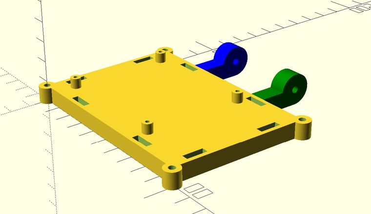
Here is the listing for the Raspberry Pi base. I have this saved this as "20x4LCDPiMountBase.scad".
// Dr.Gerg's Pi Mount for use with 20x4 LCD Mount.
// Flat mount plate for Raspberry Pi with legs to match LCD legs.
// Also has square holes for optional sides and
//     round holes for standoffs to support optional top.
// OpenSCAD definition file
// https://www.drgerg.com
// OpenSCAD Cheatsheet http://www.openscad.org/cheatsheet/index.html
use <2004 LCD Back v5.scad>;
use <3mmSocketHeadHole.scad>;
// PARAMETER DEFINITIONS
body = [98.6,69,8];                     // Main exterior shell.
lcd = [105,64,30];                      // External dimensions of LCD assembly sans legs.
leg = [19,8,8];                         // SQUARE LEG EXTENSION
hinge = 15;                             // ROUND LEG END
h_offset = leg.y - (hinge / 2);         // HINGE PIVOT HOLE OFFSET
leg_spacing = 50;                       // Distance (X) between insides of legs.
pegHole = [10.26,3.15,4];             // Dimensions for rectangular holes in base.
standDiam = 5;                          // Circuitboard standoff diameter.
SOscrewhole = 2;                        // Standoff screwhole diameter.
cornerPost = 8;                         // Dimension of corner post position.
PSH = [58,49,0];                        // Pi Mounting Screw Holes spacing.
pshMargin = 10;             // establish a margin for centering Pi on base.

//
module standoff(){
    union(){
        difference(){
        $fn = 48;
        cylinder(d=standDiam,h=5);
        translate([0,0,-2])
        cylinder(d=SOscrewhole,h=10);
        }
    }
}
//
module Leg(){                   // LEG DEFINITION
    difference(){
        union(){
            $fn = 48;              // LEG EXTENSION ($fn increases the number of faces)
            translate([0,0,0])
            rotate([0,90,0])
            cube(leg);

            translate([0,h_offset,-leg.x])  // PIVOT aka HINGE BODY
            rotate([90,0,90])
            cylinder(8,d=hinge,true);
        }
            $fn = 48;                      // PIVOT HOLE
            translate([-2,h_offset,-leg.x])
            rotate([90,0,90])
            cylinder(12,d=3.3,true);

    }
}
// OPTIONAL BACK. Uncomment to see the LCD back aligned with the base.
//
// module back(){
//     rotate([180,0,0])
//     translate([body.x/2 - lcd.x/2,-(body.y + leg.x) - (lcd.y + leg.x) - hinge/2 + 2.5,-hinge])
//     LCDBack();
// }
// back();                              // Uncomment to see the back applied to the model.

//
//// MAIN BODY OF BUILD
// COMPONENT BODY DEFINITION
//
module main(){
    union(){                                    // MAKE EVERYTHING A UNIT (MANIFOLD)
        $fn=48;
        cube(body);
        cylinder(d=cornerPost,body.z);
        translate([body.x,0,0])
        cylinder(d=cornerPost,body.z);
        translate([body.x,body.y,0])
        cylinder(d=cornerPost,body.z);
        translate([0,body.y,0])
        cylinder(d=cornerPost,body.z);
        //
        // Standoffs for Pi PCB.
        //
        translate([pshMargin,pshMargin,body.z])
        standoff();
        translate([pshMargin + PSH.x,pshMargin,body.z])
        standoff();
        translate([pshMargin + PSH.x,pshMargin + PSH.y,body.z])
        standoff();
        translate([pshMargin,pshMargin + PSH.y,body.z])
        standoff();
    }
}
difference(){
    main();
    translate([0,0,-1])
    SocHdHole();
    translate([body.x,0,-1])
    SocHdHole();
    translate([body.x,body.y,-1])
    SocHdHole();
    translate([0,body.y,-1])
    SocHdHole();
    // Rectangle Peg Holes
    // horizontal
    translate([19.5,2,body.z - 3])
    cube(pegHole);
    translate([19.5 + 48.5,2,body.z - 3])
    cube(pegHole);
    translate([19.5 + 48.5,body.y - (pegHole.y+2),body.z - 3])
    cube(pegHole);
    translate([19.5,body.y - (pegHole.y+2),body.z - 3])
    cube(pegHole);
    // vertical
    rotate([0,0,90])
    translate([9,-(pegHole.y+2),body.z - 3])
    cube(pegHole);
    rotate([0,0,90])
    translate([9,-body.x+2,body.z - 3])
    cube(pegHole);
    rotate([0,0,90])
    translate([39+9,-(pegHole.y+2),body.z - 3])
    cube(pegHole);
    rotate([0,0,90])
    translate([39+9,-body.x+2,body.z - 3])
    cube(pegHole);

}
// //
// // Standoffs for Pi PCB.
// //
// translate([pshMargin,pshMargin,body.z])
// standoff();
// translate([pshMargin + PSH.x,pshMargin,body.z])
// standoff();
// translate([pshMargin + PSH.x,pshMargin + PSH.y,body.z])
// standoff();
// translate([pshMargin,pshMargin + PSH.y,body.z])
// standoff();
//
// LEGS
//
translate([body.x/2 + (leg_spacing/2 - .3),body.y,leg.y])                      // The '.3' is the thickness of a single steel washer.
rotate([90,180,0])
color("green")
Leg();

translate([body.x/2 - (leg_spacing/2 - leg.y - .3),body.y,leg.y])              // The '.3' is the thickness of a single steel washer.
rotate([90,180,0])
color("blue")
Leg();
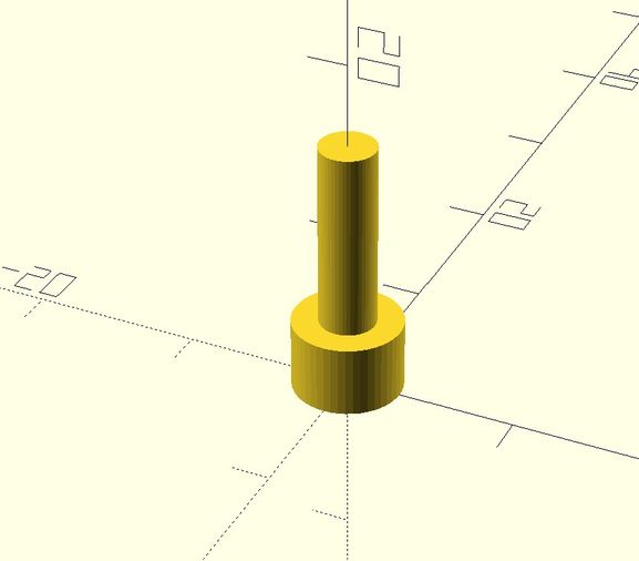
This is the listing for the 3mm Screw Hole. This file is "used" or imported in the other files, so it needs to be saved in the same folder using the name: "3mmSocketHeadHole.scad".
//Dr.Gerg's 3mmSocketHeadHole
//
// OpenSCAD definition file
// https://www.drgerg.com
// PARAMETER DEFINITIONS
cylaH = 4.2;
cylaD = 6.4;
cylbH = 12;
cylbD = 3.3;
module SocHdHole(){
$fn=48;
cylinder(cylaH,d=cylaD,false);
translate([0,0,cylaH-1])
cylinder(cylbH,d=cylbD,false);
}
SocHdHole();
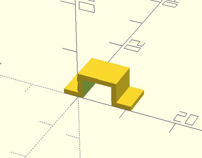
Finally, this is the file for "6mm_sq_pushbutton_holder.scad" which does what its name implies.
If you want, you can read more about it here.
// Dr.Gerg's 6mm_sq_pushbutton_holder
// OpenSCAD definition file
// https://www.drgerg.com
// OpenSCAD Cheatsheet http://www.openscad.org/cheatsheet/index.html
//
hollow = [6,8,5.2];                     // Main exterior shell.
shell = [8,6,5.2];                      // Cutter to hollow the box.
shfloor = [14,6,1];                     // Cutter for exterior indention on bottom edge.
//
//
difference(){
    translate([-3,0,0])
    cube(shfloor);
    translate([1,-1,-1])
    cube(hollow);
}
difference(){
    $fn=48;
    cube(shell);                                // Main Shell.
    translate([1,-1,-1])
    cube(hollow);                               // Hollow.

    }
