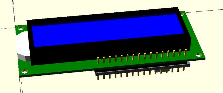
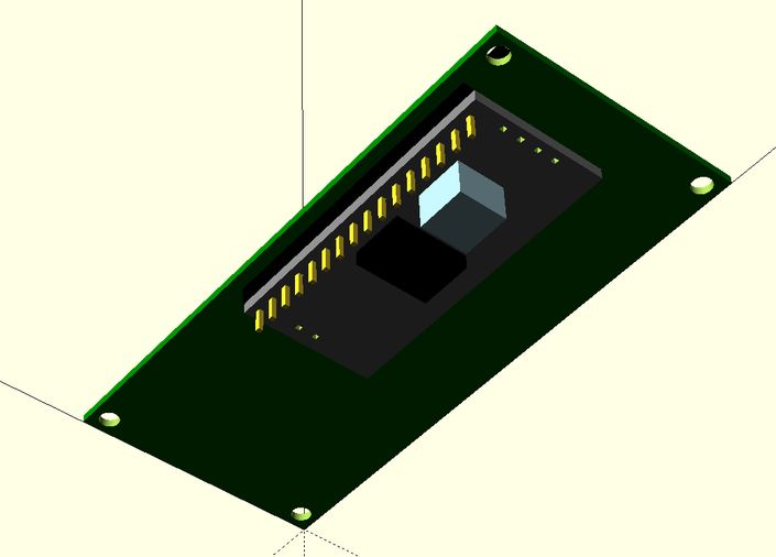
Here's another model in my project. It's a 2-row 16 character per row LCD screen with an i2c interface module attached. I'll be using this to display whatever I want on my portable project.
You may be wondering what the value of this is. The value is in fitting this model into whatever project enclosure I'm building in OpenSCAD. I use this as a module in the enclosure file to make sure the parts line up properly and there is room for everything.


Here's the code. One file for each board, and the LCD board imports the i2c board's module function:
//Dr.Gerg's i2c interface board
// for 1602A-4 16x2 and 2004 20x4 LCD modules
// OpenSCAD definition file
// https://www.drgerg.com


module hw061(){
    pcb = [18.85,41.72,1.56];
    module pin(tx,ty,tz,ry,cl,cx,cy){
        translate([tx,ty,tz])
        rotate([0,ry,0])
        cube([cl,cx,cy],false);
    }

    $fn=48;
    difference(){
    color("gray")
    cube(pcb);
    translate([1.64,1.64,-.5])
    rotate([0,0,90])
    for (i=[0:15])
        pin(i*2.54,0,0,270,3,.64,.64);
    translate([6.98,1.64,-.5])
    rotate([0,0,0])
    for (i=[0:1])
        pin(i*2.54,0,0,270,3,.64,.64);
    translate([5.55,pcb.y-1.64,-.5])
    rotate([0,0,0])
    for (i=[0:3])
        pin(i*2.54,0,0,270,3,.64,.64);
    }
    color("lightblue")
    translate([4.27,27.14,pcb.z])
    cube([6.75,6.75,5.15]);
    color("black")
    translate([4.27,15.88,pcb.z])
    cube([10.4,7.4,2]);
}
hw061();
//Dr.Gerg's 1602A-4 16x2 LCD module
//
// OpenSCAD definition file
// https://www.drgerg.com

use <hw-061 i2c LCD module.scad>;
holespcx = 33.86;
holespcy = 77.9;
mntholedia = 2.7;
pcb1 = [36,80,1.13];
lcd = [24.40,69.28,6.57];
lscrn = [16.28,65.19,1]; // lcd screen
lsc = [1,0.1,0];                    // lcd screen corner
LEDpoly = [[2.625,0],[15.125,0],[17.75,3.25],[17.75,5.35],[0,5.35],[0,3.25]];
module pin(tx,ty,tz,ry,cl,cx,cy){
    translate([tx,ty,tz])
    rotate([0,ry,0])
    cube([cl,cx,cy],false);
    translate([-2,-1,5])
    color("black")
    cube([40.5,2.54,2.54],false);
}
module screen(){
    minkowski(){
        cube([lscrn.x - lsc.x*2,lscrn.y - lsc.x*2,lscrn.z]);
        cylinder(r=lsc[0],h=lsc[1]);
    }
}
module light(){
    linear_extrude(3)
    polygon(LEDpoly);
    }
$fn=48;
difference(){
color("green")
cube(pcb1);
translate([(pcb1.x/2)-((holespcx-mntholedia)/2),(pcb1.y/2)-((holespcy-mntholedia)/2),0])
cylinder(h=6,d=mntholedia,center=true);
translate([(pcb1.x/2)+((holespcx-mntholedia)/2),(pcb1.y/2)-((holespcy-mntholedia)/2),0])
cylinder(h=6,d=mntholedia,center=true);
translate([(pcb1.x/2)-((holespcx-mntholedia)/2),(pcb1.y/2)+((holespcy-mntholedia)/2),0])
cylinder(h=6,d=mntholedia,center=true);
translate([(pcb1.x/2)+((holespcx-mntholedia)/2),(pcb1.y/2)+((holespcy-mntholedia)/2),0])
cylinder(h=6,d=mntholedia,center=true);
};
translate([pcb1.x/2 - 17.25/2,0,pcb1.z])
color("white")
light();
difference(){
    color("black")
    translate([pcb1.x/2 - lcd.x/2,pcb1.y/2 - lcd.y/2,pcb1.z])
    cube(lcd);
    color("blue")
    translate([pcb1.x/2 - lscrn.x/2 +lsc.x,pcb1.y/2 - lscrn.y/2 + lsc.x,lcd.z-lscrn.z+1.1])
    screen();
}
translate([33.3,33.9875,-7.7])
rotate([0,0,90])
for (i=[0:15])
    pin(i*2.54,0,0,270,12,.64,.64);
translate([34.3,32.4,-3])
rotate([0,180,0])
hw061();
